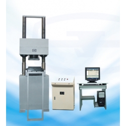
YAW-3000A Hydraulic Concrete Compression Testing Machine
 Featured
 |
Coating Thickness Gauge TIME2510
$0.00 |
 |
Surface Roughness Tester TR100
$800.00 |
 |
TIME Portable Hardness Tester TIME5104 (TH174)
$0.00 |
 |
Ultrasonic Thickness Gauge TIME2130 (TT300)
$0.00 |
 Click to enlarge |
|
Function and structure
YAW-3000A computer controlled servo hydraulic concrete compression testing machine is mainly used to various materials compression test. Such as cement, concrete, brick of diverse materials, rubber tray, concrete component, metal component anti-compress strength.
This machine is consisted of load frame, servo oil source, control cabinet, computer and printer etc. It adopts hydraulic load, oil pressure transducer to measure load, auto control the testing process by PC-hydraulic servo system. PC screen display the test data and curve, with data analysis, storage and print function.
The oil cylinder is at bottom of load frame, movable crosshead can random adjust testing space within a range. The load frame is consisted of crosshead, leading screw, working table and dolly. The crosshead is supported on base by two columns, then tighten by screw cap. On crosshead there mounted sphere base, upper platen is fixed on sphere base. When loading, it can judge the loading direction in accordance with specimen shape to make load uniformity. On crosshead mounted an adjusting motor, the motor drive worm shaft, and worm shaft drive worm wheel, then rotate the screw nut, to realize the moving of crosshead and adjusting of testing space. To support the weight of crosshead, there installed a spring in it, eliminate vertical clearance between nut screw thread and rod screw thread, make the test reliable and data accurate. Oil cylinder and piston are key part of load frame, their interface must be processed precisely, keep certain clearance and oil film. When the high pressure oil enters into oil cylinder, push piston and dolly, lower platen rising, make load consistently on the specimen. Lower platen installed on the dolly, the dolly can move easily on the orbit, it’s convenient to load and unload the specimens.
Hydraulic system theory: load adjustable input oil and throttle timing system. Hydraulic oil in the oil box is driven by high pressure gear through motor enter into the oil pipe, flow by single direction valve, high accuracy filter, time difference valve group, servo valve, then enter into oil cylinder. The computer give a signal to servo valve to control it on/off and the direction, then adjust the flux of the oil to cylinder, all of above procedure realize uniform velocity load, relatively displacement etc.
Main specification
|
No. |
Item |
Specification |
|
1 |
Max. capacity (KN) |
3000 |
|
2 |
Measuring range |
4%-100% of FS |
|
3 |
Relative error of reading |
≤±1% |
|
4 |
Uniform velocity stress control range(N/mm²·S¯¹) |
1-10 |
|
5 |
Stress velocity error |
≤±5% |
|
6 |
Max. distance between two platen (mm) |
1000 |
|
7 |
Compression platen size (mm) |
400*400 |
|
8 |
Max. piston stroke (mm) |
0-200 |
|
9 |
Max. piston speed (mm/min) |
Approx. 35 |
|
10 |
Column clearance (mm) |
560 |
|
11 |
Oil pump motor power (KW) |
5.5 |
|
12 |
Moving motor power(KW) |
1.5 |
|
13 |
Load frame dimensions (mm) |
1000*1480*3400 |
|
14 |
Cabinet dimensions (mm) |
600*480*960 |
|
15 |
Load frame weight (KG) |
Approx. 7000 |
Standard accessories
|
No. |
Item |
Specification |
Quantity |
Remarks |
|
1 |
Load frame |
|
1 set |
|
|
2 |
Oil source control cabinet |
|
1 set |
|
|
3 |
Proportion valve |
|
|
|
|
4 |
Oil pressure transducer |
GYB-12SA |
1 pc |
|
|
5 |
Photoelectric encoder |
|
|
|
|
6 |
Measuring and control system |
|
1 set |
|
|
7 |
Computer |
P4/256MDDR/80G |
1 set |
LENOVO |
|
8 |
Printer |
HP1368(A4,ink jet) |
1 set |
HP |
|
9 |
Upper and lower platen (mm) |
400*400 |
1 set |
|
|
10 |
Tool kits |
|
1 set |
|
|
11 |
Accessoried documents |
|
1 set |
|
Your Review: Note: HTML is not translated!
Rating: Bad Good
Enter the code in the box below:


 Categories
